Ball mill
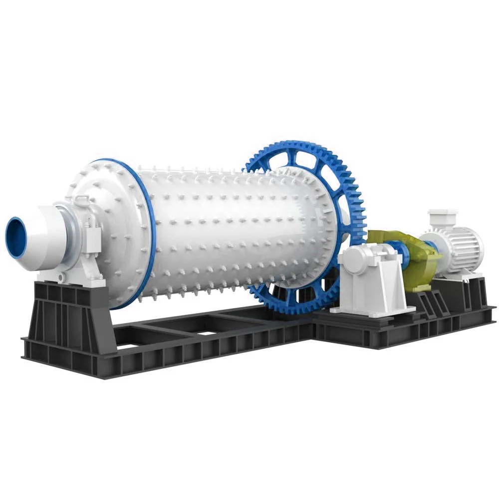
A horizontal rotating drum that grinds material with a charge of steel balls — the workhorse for wet or dry mineral grinding ahead of classification or flotation.
What it does and where it fits
The ball mill grinds feed inside a slowly rotating drum, where a charge of steel balls cascades and crushes the material to a target fineness. It runs in wet or dry mode and pairs with a classifier for closed-circuit grinding. Rugged and simple, it is a long-serving choice across mineral-processing lines, with drum sizes scaled to throughput. The energy-saving variant uses rolling-bearing support in place of sliding bearings, cutting power use by 10–20%.
- Handles wet or dry grinding of a wide range of ores.
- Simple, rugged construction — long service life and easy maintenance.
- Pairs with a classifier for closed-circuit grinding to a target fineness.
- Scalable drum sizes to match throughput.
What sets it apart — point by point
Wide application
Many types and sizes suit a wide range of industries, from powder making to mineral dressing.
High crushing ratio
The crushing ratio can reach 300 and the finished fineness is adjustable.
Large capacity
Meets the throughput of large-scale mineral dressing production lines.
Stable performance
Novel structure, easy and safe to operate, stable and reliable running with noticeably reduced downtime.
Lower investment, energy saving
Rolling-bearing support replaces sliding-bearing support, saving 10–20% energy for a lower total investment.
Typical configurations — sized to your capacity
| Drum Ø×L (mm) | Speed (r/min) | Ball load (t) | Input (mm) | Output (mm) | Capacity (t/h) | Power (kW) | Weight (t) |
|---|---|---|---|---|---|---|---|
| Ø900×1800 | 36–38 | 1.5 | ≤20 | 0.075–0.89 | 0.65–2 | 18.5 | 4.6 |
| Ø900×3000 | 36 | 2.7 | ≤20 | 0.075–0.89 | 1.1–3.5 | 22 | 5.6 |
| Ø1200×2400 | 36 | 3 | ≤25 | 0.075–0.6 | 1.5–4.8 | 30 | 12 |
| Ø1200×3000 | 36 | 3.5 | ≤25 | 0.074–0.4 | 1.6–5 | 37 | 12.8 |
| Ø1200×4500 | 32.4 | 5 | ≤25 | 0.074–0.4 | 1.6–5.8 | 55 | 13.8 |
| Ø1500×3000 | 29.7 | 7.5 | ≤25 | 0.074–0.4 | 2–5 | 75 | 15.6 |
| Ø1500×4500 | 27 | 11 | ≤25 | 0.074–0.4 | 3–6 | 90 | 21 |
| Ø1500×5700 | 28 | 12 | ≤25 | 0.074–0.4 | 3.5–6 | 130 | 24.7 |
| Ø1830×3000 | 25.4 | 11 | ≤25 | 0.074–0.4 | 4–10 | 130 | 28 |
| Ø1830×4500 | 25.4 | 15 | ≤25 | 0.074–0.4 | 4.5–12 | 155 | 32 |
| Ø1830×6400 | 24.1 | 21 | ≤25 | 0.074–0.4 | 6.5–15 | 180 | 34 |
| Ø1830×7000 | 24.1 | 23 | ≤25 | 0.074–0.4 | 7.5–17 | 210 | 36 |
| Ø2100×3000 | 23.7 | 15 | ≤25 | 0.074–0.4 | 6.5–36 | 210 | 34 |
| Ø2100×4500 | 23.7 | 24 | ≤25 | 0.074–0.4 | 8–43 | 245 | 42 |
| Ø2100×7000 | 23.7 | 26 | ≤25 | 0.074–0.4 | 8–48 | 280 | 50 |
| Ø2200×4500 | 21.5 | 27 | ≤25 | 0.074–0.4 | 9–45 | 280 | 48.5 |
| Ø2200×6500 | 21.7 | 35 | ≤25 | 0.074–0.4 | 14–26 | 370 | 52.8 |
| Ø2200×7000 | 21.7 | 35 | ≤25 | 0.074–0.4 | 15–28 | 380 | 54 |
| Ø2200×7500 | 21.7 | 35 | ≤25 | 0.074–0.4 | 15–30 | 380 | 56 |
| Ø2400×4500 | 21 | 30 | ≤25 | 0.074–0.4 | 8.5–60 | 320 | 65 |
| Ø2700×4000 | 20.7 | 40 | ≤25 | 0.074–0.4 | 12–80 | 400 | 94 |
| Ø2700×4500 | 20.7 | 48 | ≤25 | 0.074–0.4 | 12–90 | 430 | 102 |
| Ø3200×4500 | 18 | 65 | ≤25 | 0.074–0.4 | 25–130 | 800 | 137 |
Material in, finished powder out — the running flow
Feeding
Material is transferred into the grinding chamber through the quill shaft uniformly.
Impact & grinding
The horizontal drum rotates via the outer gear. Ladder and ripple liners lift the steel balls, which impact and grind the material as they fall.
Discharge
Ground material is discharged through the discharging board, finishing the grinding process.
A closer look
Images are representative — on-site photography of your configuration is pending.
Suited to a range of brittle minerals
Material list is a demonstration placeholder. Hardness, moisture and target fineness are subject to engineer assessment.
Send your material and target fineness — we'll match the right mill.
Engineers review every enquiry line by line and return an initial model pick and whole-line proposal within one working day.